Friday, October 31, 2008

TouchShield Tetris

When I was little, this game kept me up for hours past by bed time! Besides, what else would a normal person be doing at that time anyways?

The Tetris source code for the TouchShield can be found on the projects page along with Arduino code for interfacing to the InputShield. Simply copy and paste to try it out!


Wednesday, October 29, 2008

A humble little GamePack game :)

I've never gotten so many emails in my life! Wow... well, I really like all the emails I've read, but of course I also like the funny comments some folks posted over on digg (and I know the comment about inventing fire was meant to be a joke, but how cool would it be to have a fire / pyrotechnic shield controller?). Oh well, I suppose you can't please all the people all the time. :) Anyway, I'm just finishing up the spec sheet and I'll post the schematics and wiring diagrams over at liquidware.org. A handful of emails asked about how to read values off the joystick, and it's fairly easy (but only because Arduino environment is so straightforward):

  • The InputShield connects the joystick x and y axis to the analog input pins
  • I use the Arduino command analogRead(4) and analogRead(5) to get x and y respectively
  • Those values come in as integers, between 0 and 1024, and the joystick is a resistive voltage divider, so the middle state means the value back from analogRead(4) is about 500, give or take. Same thing with the other axis.
  • I typically do a small calculation on the value, to set it in the right range, like check to see if it's bigger than 600 or smaller than 400, and then I know the joystick has been moved
  • The buttons are a little more straightforward, since they're either on or off
  • The buttons normally keep the digital line they're on high
  • Button A is wired to digital pin 5, and button B is wired to digital pin 4
  • I use the Arduino command digitalRead(4) and digitalRead(5) to read the value of those pins
  • Then, in my loop() function, I write code like if(!digitalRead(4)), which means if the value is not not high, then do something

I put all that together in a little piece of source code, to make a really simple game. The game has little orbs that fall down towards the bottom of the screen, and you have to avoid them. If you hit one, then the little ball you control gets dimmer. To make your little ball brighter, you have to run into the little blue orbs, which are life points. If you hit button b, it pauses and unpauses the game, and button a is a "cheat" which resets you to full life. Next stop, tetris! Just kidding :)


Of course, here's the source code - I tried to comment it (which I'm not too good about, but I tried):


COLOR green = { 0, 255, 0 };
COLOR blue = {0,0,255};
COLOR yellow = {255,255,0};
COLOR black = {0,0,0};
COLOR white = {255,255,255};
COLOR grey = {0x77,0x77,0x77};
COLOR red = {255,0,0};
COLOR me = {0,255,0};

POINT my_point;//i'm not using the touchscreen for this, but maybe i will next time

unsigned int analogValues[6];
unsigned char digitalValues[10];

int pos = 64; //my position at the bottom of the screen - 64 is the middle of the 128 screen

#define NUMBLOCKS 10 //i can make more orbs by making the numblocks bigger
int xs[NUMBLOCKS];//x positions of the orbs
int ys[NUMBLOCKS];//y positions
int ds[NUMBLOCKS];//d stands for delta, or how much the orb should move
int t[NUMBLOCKS];//type of orb (good or bad)

#define DIFFICULTY 4 //the bigger the number, the faster the starting velocity of blocks...

int timer,go;
unsigned char lives=10;

void setup()
{
lcd_setBrightness(5);

//initiatlize the orbs
for(int i=0;i<NUMBLOCKS;i++){
xs[i]=(int)(90+(rand()%100));
ys[i]=(int)(10+(rand()%80));
ds[i]=2+(int)((rand()%10));
t[i]=1;
}

timer = 0;
go = 0;

Serial.begin(9600);
delay(3000);

/* The sync character */
Serial.print('U');
}


void loop()
{
//digitalValues[0] - digital pin 4, button B MODEA
//digitalValues[1] - digital pin 5, button A MODEA
//analogValues[5] - joystick y, MODEA
//analogValues[4] - joystick x, MODEA

//Read analog values - for x and y position of the joystick
analogValues[4] = (Serial.read() << 8) + Serial.read();
analogValues[5] = (Serial.read() << 8) + Serial.read();

//Read digital values for buttons a and b state
digitalValues[0] = Serial.read();
digitalValues[1] = Serial.read();

if (!digitalValues[1]) {//if button a is pressed, give me more life
me.green=255;
}
if (!digitalValues[0]) {//if button b is pressed, pause the game
go=!go;//go has to be 1 in order for the orbs to fall down
}

eraseCar();//erase car

//update coordinates of the car based on the joystick position
//the further over the joystick is leaned, the more the car moves
if (analogValues[4] < 400) pos += 2;
if (analogValues[4] > 600) pos -= 2;

if (analogValues[4] < 200) pos += 2;
if (analogValues[4] > 800) pos -= 2;
if (analogValues[4] < 100) pos += 2;
if (analogValues[4] > 900) pos -= 2;

if (pos < 10) pos = 10;//keep the car in bounds
if (pos > 118) pos = 118;

drawCar();//draw car

if (go && timer++ >= 0) {//if i wanted to debug and slow things down, i make 0 a bigger number, like 5
timer = 0;
eraseCascade();//erase the orbs
cascadeDown();//make them go down
drawCascade();//draw them again
}

}


void drawCar(void) {
//draw me, me is a global variable for the rgb color
lcd_circle(5,pos,5, me, me);
}

void eraseCar(void) {
//erase me
lcd_circle(5,pos,5, black, black);
}

void cascadeDown(void){
for(int i = 0; i<NUMBLOCKS; i++) {
//xs[i]-=5; //orbs cascade down at fixed speed
xs[i]-=ds[i]; //orbs cascade down at variable speed

if(xs[i]<5) {//are the orbs at the bottom of the screen>
if ((ys[i]>(pos-6)) && (ys[i]<(pos+6))){//is the orb on top of the car?
if (t[i]) {//is it a 'bad' orb? if so, dim the color
me.green-=40;
if(me.green<20) me.green = 20;
} else {//is it a good orb? if so, make the car brighter
me.green+=40;
if(me.green>255) me.green = 255;
}

}
//assign new random coordinates and speed to the orb
xs[i] = (unsigned int)130+(rand()%20);ys[i] = (unsigned int)10+(rand()%100);ds[i]=DIFFICULTY+(int)((rand()%10));
if ((rand()%20)>18) {//a few of them will be good orbs
t[i] = 0;
} else {
t[i] = 1;
}
};
}

}

void drawCascade(void){
//repeat for number of blocks
for(int i = 0; i<NUMBLOCKS; i++) {
if (xs[i]<115 && xs[i]>5) {//only draw the orb if it's inbounds on the screen
if (t[i]) {
lcd_circle(xs[i],ys[i],2, white, white); //bad orbs are white
} else {
lcd_circle(xs[i],ys[i],2, blue, blue); //good orbs are blue
}
}
}

}

void eraseCascade(void){
//i know, i know, not the most elegant, but this just erases where the orbs where by painting over in black
for(int i = 0; i<NUMBLOCKS; i++) {
if (xs[i]<115) {
lcd_circle(xs[i],ys[i],2, black, black);
}
}

}

Tuesday, October 28, 2008

The open source hardware cast of characters

For those just tuning in, I pulled together a little play called Open Source Hardware, Vol 1. If my English teacher taught me anything from those paperback copies of Shakespeare (you know, the ones with the notes on every other page that make the book twice as long), it's that every play must start with a "cast of characters". So before Act I, Arduino, comes "Introduction to the modules" over on the wiki. I also put in some definitions that I thought were useful as a start, so please feel free to add to the list!

Monday, October 27, 2008

Using the InputShield to make an Open Source Game boy

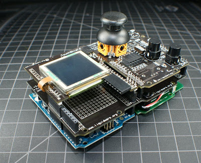
Ok, so ever since middle school I've wanted to make one of these... but I only now have enough know-how and support to make it, ... an Open Source game boy :) Actually, it's a little smaller than a game boy, but it's 1000% cooler (in my opinion) because it uses an Arduino as the "core", and a few modules and shields that already exist.


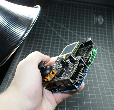
Here are a couple other pictures of the GamePack (it's like the GadgetPack, except in the free spot, I put the InputShield)... makes me wish I had a "hand model" like in Zoolander - ha:


Then I took a photo a little further back, and it had the cheapo home depot construction light that my friend uses to light up stuff (with a fluorescent bulb) in the picture, and it kind of looked like an alien was looking down at it, so I kept it:


I took this video as soon as I had everything up and running, and it's running the source code that's pasted at the bottom of the post...


Here's another video of pretty much the same thing...


I don't know if I really like the lighting in the videos, but I'm not a professional video taker, so I'll have to read up some books at Barnes and Noble around the corner and try to figure it out. I'm still using the same Aiptek mini HD recorder, and not some fancy equipment.

Anyway, here's the source code that runs on the Arduino:


#include

#define RXPIN 3
#define TXPIN 2

AFSoftSerial mySerial = AFSoftSerial(RXPIN, TXPIN);

unsigned char x=0;

void setup()
{
mySerial.begin(9600);

/* Sync up by waiting for character */
while(mySerial.read() != 'U');
}


void loop()
{
/* The first analog pin sent */
x=0;

/* send 6 Analog Pin values */
while (x <>
{
serial_sendAnalog(x);
x++;
}

delay(10);

x=0;
while(x<>
{
serial_sendDigital(x);
x++;
}

delay(100);

}

void serial_sendDigital(unsigned char digitalPin)
{

if ( (digitalPin <> 13) )
return;

mySerial.print((unsigned char)digitalRead(digitalPin));
delay(2);

}


void serial_sendAnalog(unsigned char analogPin)
{
unsigned char lowByte, highByte;
unsigned int val;

/* Pin number range check */
if (analogPin > 6)
return;

/* Get the value */
val = analogRead(analogPin);

/* Separate the value into 2 bytes */
lowByte = (unsigned char)val;
highByte = (unsigned char)(val >> 8);

/* Send the high byte */
mySerial.print(highByte);

/* Write delay */
delay(1);

/* Send the low byte */
mySerial.print(lowByte);

/* Write delay */
delay(1);
}


And here's the source code that goes on the TouchShield:


COLOR green = { 0, 255, 0 };
COLOR blue = {0,0,255};
COLOR yellow = {255,255,0};
COLOR black = {0,0,0};
COLOR white = {255,255,255};
COLOR grey = {0x77,0x77,0x77};
COLOR red = {255,0,0};

POINT my_point;

unsigned int analogValues[6];
unsigned char digitalValues[10];

LCD_RECT digitalRect = { 118, 15, 127, 115 };
LCD_RECT analogRect = {0, 60, 32, 121 };

unsigned char x;

void setup()
{

Serial.begin(9600);
delay(3000);

/* The sync character */
Serial.print('U');
}

unsigned int oldx, oldy, newx, newy;
int erasemode = 2;
int pencolor = 1;


void loop()
{
//digitalValues[0] - digital pin 4, button A MODEA
//digitalValues[1] - digital pin 5, button B MODEA
//digitalValues[4] - digital pin 8, button A MODEB
//digitalValues[5] - digital pin 9, button B MODEB
//analogValues[5] - joystick y, MODEA
//analogValues[4] - joystick x, MODEA
//analogValues[3] - joystick y, MODEB
//analogValues[2] - joystick x, MODEB

//Read analog values

analogValues[0] = (Serial.read() <

<>
analogValues[1] = (Serial.read() <

<>
analogValues[2] = (Serial.read() <

<>
analogValues[3] = (Serial.read() <

<>
analogValues[4] = (Serial.read() <

<>
analogValues[5] = (Serial.read() <

<>

//Read digital values:

//Read digital values
digitalValues[0] = Serial.read();
digitalValues[1] = Serial.read();
digitalValues[2] = Serial.read();
digitalValues[3] = Serial.read();
digitalValues[4] = Serial.read();
digitalValues[5] = Serial.read();
digitalValues[6] = Serial.read();
digitalValues[7] = Serial.read();
digitalValues[8] = Serial.read();
digitalValues[9] = Serial.read();

if (touch_get_cursor(&my_point)) {
lcd_clearScreen( black);
}

newx=3+(1023-analogValues[5])*.12;
newy=3+(1023-analogValues[4])*.12;

if (erasemode && ((oldx != newx) (oldy != newy))) {
lcd_circle(oldx,oldy,5, black, black);
}
if (pencolor == 1) {
lcd_circle(newx,newy,5, blue, blue);
} else if (pencolor == 2) {
lcd_circle(newx,newy,5, green, green);
} else if (pencolor == 3) {
lcd_circle(newx,newy,5, red, red);
} else {
lcd_circle(newx,newy,5, white, white);
}

if (!digitalValues[0]) {
erasemode = !erasemode;
}

if (!digitalValues[1]) {
pencolor++;
if (pencolor == 5) {
pencolor = 1;
}
}

oldx=newx;
oldy=newy;
}


Introducing the InputShield

The InputShield is a shield for the Arduino that gives it a joystick and two buttons (A and B). That means I can connect it on top of the Arduino, and read in the X and Y coordinates over the analog input pins. I can also read the values of buttons 1 and 2 with digital read functions, so it's pretty straightforward to code too (code at the bottom).


I glued a small vibrator motor to the back of the board too, so it can be used to give a little bit of "force feedback" :-) I don't have a clean shot of the back yet, but here are some up-close pictures. You can see the double-stacked right angle female pin header on the top of the board, which I put so I can still fit solid core wires in and access power, ground, and the other digital pins (for when I wire up an accelerometer):


The InputShield comes with PCB traces for different types of layouts (partly because Chris is a lefty and I'm a righty). That way, when it's a kit, I can solder the joystick or buttons in one configuration or the other:

My friend showed me how to take 3D perspective shots like he used to, so believe it or not... I actually took this photo! (no, seriously... although I didn't set up the lighting or the camera settings - I don't even know what camera settings mean or do):


I spent almost all weekend soldering a few of these up, and then taking photos with the camera (they're all on Flickr), and I also wrote some small code to read the values using the Arduino:


void setup()
{
Serial.begin(9600);
pinMode(7,OUTPUT);
digitalWrite(7,LOW);

pinMode(11,OUTPUT);
digitalWrite(11,HIGH);

digitalWrite(4, HIGH); pinMode(4, INPUT);
digitalWrite(5, HIGH); pinMode(5, INPUT);
digitalWrite(6, HIGH); pinMode(6, INPUT);

digitalWrite(8, HIGH); pinMode(8, INPUT);
digitalWrite(9, HIGH); pinMode(9, INPUT);
digitalWrite(10, HIGH); pinMode(10, INPUT);
}


void loop()
{
Serial.print(" L1: ");
Serial.print((unsigned int)analogRead(5));
Serial.print(" V1: ");
Serial.print((unsigned int)analogRead(4));
Serial.print(" L2: ");
Serial.print((unsigned int)analogRead(3));
Serial.print(" V2: ");
Serial.print((unsigned int)analogRead(2));

Serial.print(" B1: ");
Serial.print((unsigned int)digitalRead(4));
Serial.print(" B2: ");
Serial.print((unsigned int)digitalRead(5));
Serial.print(" B3: ");
Serial.print((unsigned int)digitalRead(6));

Serial.print(" B5: ");
Serial.print((unsigned int)digitalRead(8));
Serial.print(" B6: ");
Serial.print((unsigned int)digitalRead(9));
Serial.print(" B7: ");
Serial.print((unsigned int)digitalRead(10));

Serial.print("\n");
digitalWrite(7,LOW);
delay(200);
digitalWrite(7,HIGH);
delay(200);
}

I'll put the InputShield up on the store over at Liquidware... and I'll also upload a couple of videos of the other stuff I made with it.

Friday, October 24, 2008

Getting to know your Arduino...

It's been crazy busy over here, so I haven't had a chance to put up too much over on the wiki. So with what time I did have, I uploaded the most basic, fundamental chapter- Getting to know your Arduino! For the true beginner, like myself. Actually, Matt and I had a little debate over what to put in here, but we ended up keeping it on the leaner side. So if you've got something to add, here's your chance to do it!

On another note- thanks for all the support on the book! I've shipped a couple out and only have one copy left (okay so I didn't start out with that many) but quite thrilled nonetheless. I can't wait to get some input as the book on open source hardware itself becomes open source!

Tuesday, October 21, 2008

Arduino: Custom Analog Voltage

If you’re like me, you always want what you can't have. Today it's an analog voltage output on Arduino's on pin 12.


The beauty of open source hardware and the Arduino is that there's a ton built-in functions. However, for a Pin Visualizer project I was working on I needed to output an analog voltage on a pin that didn't have hardware PWM.

So here's is a way to put an Analog Voltage on any pin.


Parts:

1. Arduino
2. 500 ohm resistor
3. 1uF Capacitor

Code:

/****************************/
/* Title: PWM on any pin */
/* By: Chris Ladden */
/* www.liquidware.org */
/****************************/

/* Analog output pin */
#define ANALOG_PIN 12

/* The PWM period. For smaller output caps, make this shorter */
#define PWM_PERIOD 100

void setup()
{
/* Make the pin an output */
pinMode(ANALOG_PIN, OUTPUT);
}

/* 20 = 20% duty cycle = 1.0 VDC */
/* 50 = 50% dutyCycle = 1.2 VDC */
/* 70 = 70% duty cycle = 3.5 VDC */
unsigned char dutyCycle=70;
volatile unsigned char x;

void loop()
{
/* Pin output, high */
digitalWrite(ANALOG_PIN, HIGH);
for (x=0;x

/* Pin output, low */
digitalWrite(ANALOG_PIN,LOW);
for (x=0;x< (PWM_PERIOD-dutyCycle);x++) { ; }
}

Open Source Hardware book - Table of Contents

Here's the table of contents for the Open Source Hardware book. One of the original ideas of the book was to help students of industrial or product design classes use the Arduino as a platform to build gadgets and devices. I took a course similar to that a long time ago, and was frustrated that the course never got past switches and LED circuits. I had the hardest time extrapolating from what I was learning to image how I was actually going to use what I learned to build a real product.

Instead, Justin and I organized the book as though I was taking the class all over again. First I would have wanted to know a little about the concepts, and what open source hardware and gadget design was all about. Then, I'd want to spend a brief time on the basics, but mostly dive straight into the design of an actual gadget. So at the end of it all, I hope the book reads like that course could have gone (maybe in a parallel universe).

When I took the course, my final project was a "simple simon" game circuit (the kind where it plays a sequence on 4 LED buttons, and you have to type it back in the same order). I like to think that if I had this book back then, my final project would have been an MP3 player, or GPS device (which is what I had wanted to make in the first place!).


Open Source Hardware - Volume 1
Do-It-Yourself Gadgets


Foreword.. i

Introduction.. 1
  • What is open source hardware?. 1
  • What is physical computing?. 3
  • What are modular electronics?. 5
  • What is the Arduino?. 6

How to use this book. 8

Getting to know your Arduino.. 10
  • Landmarks on the Arduino Diecimila board.. 12
  • Installing the Arduino programs on your desktop.. 13
  • Navigating the Arduino programming environment 14
  • Introduction to the modules. 16

Terms used throughout the book. 23

Arduino.. 25
  • Hello world program... 26
  • Communicating between the Arduino and PC over serial 32
  • Blinking the onboard LED on pin 13. 38

Arduino + Breadboard + LEDs. 43
  • Knight Rider with LEDs. 44

Arduino + Digital input switches. 54

Arduino + Analog inputs. 62
  • Battery Tester 63

Arduino + Lithium Backpack. 69
  • Portable LED blinker 70

Arduino + TouchShield.. 76
  • How to Program the TouchShield.. 77
  • Basic Squares. 81
  • TouchShield Hello World.. 85
  • Reaction Time Game.. 90
  • Stoplight. 95
  • Countdown Timer 99
  • Battery Life Monitor 104

Arduino + ProtoShield + GPS. 109
  • Serial GPS reader 110

Arduino + ProtoShield + Accelerometer 117
  • Gravity Tester: Basic input and output over serial 118

Arduino + ProtoShield + Ping Sensor 128
  • Burglar Alarm... 129

Arduino + Motor board + Motor 135
  • Basic control of a motor 136

Arduino + Lithium Backpack + TouchShield.. 142
  • Pin Visualizer 143
  • BitDJ. 155

Arduino + ExtenderShield + ProtoShield + TouchShield + BackPack + Accelerometer 163
  • Acceleration meter 164

An open source project 173
Additional resources 174

My Own Device (I). 176
My Own Device (II)

Chapters from the Open Source Hardware Book

Well, there goes all the copies of the book Justin helped to write and make... it definitely seems like a lot of folks are interested in learning more about projects. I asked Justin to set aside a copy of the book for a friend of mine, who flies a lot, and codes his Arduino on flights (I can just imagine the looks he gets from anyone sitting next to him). I also got a fair number of emails over the past couple of days asking for more copies, and details, and sample chapters. So Justin and I decided to start uploading the table of contents and a few chapters of the "book" over to the wiki. It'll take some time to get all the formatting right, so I'll try my best to upload a couple of the first chapters in the next week or so (and I'll also post it here on the blog too). I guess you could sort of call it another book in the growing library of "open source hardware".


Anyway, to start things off, I wanted to pay my thanks to everyone who helped out over the past few months. The opening pages of the book includes a caption dedicating the book to:


David Mellis, Arduino Core Team

Nathan Seidle, Sparkfun

Phil Torrone, Make Magazine

David Cuartielles, Arduino Core Team

Limor Fried, Adafruit Industries

Tom Igoe, New York University


These folks were especially helpful and supportive in helping me learn the Arduino platform back when I first picked it up, so I'm especially thankful to them! However, I'm sure this list will continue to grow longer and longer over the next couple of months.

Cheers for open source hardware!

I just saw this article over at Wired online, and I have to say it makes me really proud to see so many people in a real publication that I've actually met and talked to. I think this is a really great day (month?) in general for Open Source hardware, especially now that the community is growing faster and increasingly more mainstream. In fact, one of my friends from grade school even read the article and sent it to me over email (he was definitely in for a surprise when I sent him a link to liquidware and said, yep, I know!).

(It also answers a nagging question I've had in the back of my mind... what do some of these Arduino folks actually look like... ha)

Anyway, here's one for Open Source Hardware.

Hazzah!

Monday, October 20, 2008

My mom's not as interested in the Arduino as I am

I went home this weekend carrying my newfound treasure- a shining, shimmering copy of Open Source Hardware, Volume 1: Do-It-Yourself Gadgets. It reminded me of that time I brought home my very first book report to show my mom (I got a B+, in case you're wondering, and no, it wasn't good enough).

Me: You know that electronics stuff I've been playing with? The Arduino?
Mom: Yeah?
Me: I typed up my notebook and turned it into a real book! Pictures, barcodes, and everything! It's about all the stuff I learned...maybe you want to try it out? (hand book to Mom)
Mom: (flipping through) It's so glossy...so many pictures. Where are all the words?
Me: It's supposed to be illustrative, step-by-step, so you know what you're doing...it's not a novel.
Mom: (closes book) I thought you were going to be a doctor. When are you applying to med school? You're still applying, right?
Me: (awkward silence)

Well, my mom thinks it's a nice looking book, but isn't really interested in learning about our dearest Arduino & friends, so I've got just a couple extra copies lying around from the batch I printed. Hopefully someone thinks otherwise :-) If you're interested, I have it up over on the Liquidware site.

Also, I slipped in the thinnest USB stick I could find (the Kingmax SuperStick) with source code and other handy files, so you'll really have a treasure trove of projects to get you going once you pick this up! I'm still relatively new to all of this (book printing, Arduino, GIMPShop, you name it) so I'm sure there will be another revision sometime soon!

Sunday, October 19, 2008

Duemilanove -> 2009

A new bread of the Arduino board has finally been released to the community!
  • It is called the Arduino Duemilanove (2009).
  • The new board has an automatic power select between the USB port or the DC Power plug.
  • According to David Mellis, the Duemilanove will be replacing the Diecimila.
I just bought a bunch of Duemilanoves so I can sell them on Liquidware. They aren't in stock at the current time, but I will be accepting back orders. The last I checked they were already in the mail on the way to my apartment.

I'm so excited :o)

-Mike

Friday, October 17, 2008

You've got mail...a 10 lb package, to be exact

I'm really pumped...all that money I spent on speedy shipping was so worth the near-instant gratification of having it printed and delivered in 2 days. I'm not gonna lie, I splurged a little :-) But I've never done this before, and something told me it would be way better than just having a PDF or printing it out on my good old inkjet.

And the coil bound...just seemed too much like the notebook I already had. It reminded me of a project I had in 7th grade, where we pulled together our "portfolio" of work, then sent it off to have it hardcover bound. Almost.

Alright, alright, without further ado, the first snapshots of the book! And boy does it look like a real book!! Matt, Chris, and Mike were awesome teachers throughout this whole process, so hopefully I can pass on some of what I've learned too.


Here's a shot of the book with the Arduino:

And a couple shots of how the inside turned out. The paper was great, and I'm really thrilled, if you can't tell!Well, I have a few copies and I can't wait until my friends and family see this. I'm gonna get them all hooked on the Arduino...and boy would my science teacher be proud!

Wednesday, October 15, 2008

They called me a n00b...

...And I wanted to do something about it. So I started learning to play on the Arduino. It's just one of those things you gotta jump right into, get your hands dirty- and that's just what I did. This is probably your story too.

I took notes along the way. And some pictures too. But having jumped in helter skelter, I also realize that there were some projects which would have helped me earlier, rather than later. And some stuff is just nice to build off of. So I started to organize my notebook into a booklet of tutorials for others like me.

Anyways, I began typing up my notes and organized the pictures. And what started out as a little booklet slowly became a bloated word document, and I figured, why the hell not. With all the pretty pictures I took with Matt's snazzy new camera, I really didn't want it to go to waste. Maybe I can even help out someone in my shoes :-)

I've even drafted a (very amateurish) cover in GIMPshop, and I decided to print a couple copies at Lulu.com. They even gave me a barcode!! Okay well I'm getting way too excited but I've never printed a book before, so I can't wait till they get here. Stay tuned...promise I'll post pics!

Monday, October 13, 2008

I've been busy!

The past week, I've been really busy. To begin with, I'm rushing to build everyone's TouchShields that have been ordered over the last couple weeks since the store was sold out. Justin, Mike, and I have been soldering up a storm, and testing connections, cables, you name it.

Also, I've been really busy hacking out some code for VGA, RFID, and USB. The idea is to make a fully self-contained, Arduino powered laptop with all those inputs and outputs... and I'm definitely trying my hardest to stand on the shoulders of others:

I really like Limor's data logging shield, but I think it'd be really useful to find a way to data log onto a USB drive too, since that's how I store most of my data. I also think the VGA code work is pretty cool, though it looks like there's still some ways to go before anyone hacks out small pixels. Of course, a number of folks have hacked the Parallax RFID reader, so I'm going to see if I can use some of that code too. Anyway, it's going to be a busy set of weeks, that's for sure!

Sunday, October 5, 2008

Hacking the Esquire cover e-ink screen with the Arduino


Last month, Esquire magazine published a cover that contained an E-ink screen. I was really looking forward to it, actually... so much so that I marked it in my calendar to make sure I picked one up around the corner. There was quite a bit of hype about it, and a lot of people wrote about it on their blogs and websites, and Esquire even encouraged hackers (does that include me?) to play around with the screen. The local store had a couple of copies left over this past week, so I grabbed one, and decided to see what I could do in a couple hours of playing around.


Of course the first thing I did was rip off the cover:


I noticed that the cover was a folded-over piece of card stock, so I pried it open:


The funny part was that it kept on blinking even as I took it apart... felt a bit like the scene in 2001 A Space Odyssey when the guy unplugs Hal:


This is the back-side of the device:


And this is what the front side of the PCB board looks like. The components have been identified on other sites, but suffice to say there are a lot of batteries, two shift registers, and a small PIC chip that runs the program.


I knew within a few minutes of looking at the board that I could either approach this one of 3 ways:

1-Hack the PIC chip, perhaps by reprogramming it
2-Hack into the shift registers, by cutting the input line, and taking them over... but what if they're held in some level by the PIC chip, and there's a via under the chip that I miss?
3-Hack directly into the screen (hoping that there protocol and voltage isn't too difficult to work with, and that I can safely bypass the rest of the circuit with little to no consequences).

I chose method 3, because it seemed like the most straightforward, and the one I could probably get right on the first try. The cable to the screen had 12 wires, and the PCB had resistors lined up in two rows after the connector. I soldered solid-core wire directly onto the small round pads the PCB designers left for me (thanks, guys!), in perhaps the world's sloppiest, hackiest, and odd-looking design ever. Actually, I took a perspective photo of it below, and I think it came out pretty nice!


I connected the wires from the PCB onto a white mini-protoboard - mainly because of the fragile nature of the PCB-solid core soldering job I did. Even a small jostle would disconnect the wires from the PCB, and I knew I'd be rearranging the wires quite a bit as I discovered which lead was ground, or how they were wired up. I tried a few configurations, including assuming ground was in the middle, far right, or far left of the connector. I found that by applying +5 to one lead, and 0 GND to the ground pin, I could turn a segment on. Then, I found that by applying 0 GND to the lead, and +5 to the ground pin, I could turn the segment back off. This is the same as saying the screen accepts +5 to -5 voltage as it's range, where +5 turns it on, and -5 turns it off. Ugh. That means it'll be a little tricky to work with, but I've seen worse!


Ok, so I was fairly proud of my soldering job, so here's another shot of the wires:


I connected the ground pin to the Arduino pin number 2, and all of the other pins on the first row to Arduino pins 3-7, and the second row from 8-13. I wrote a small piece of code to turn the pins on and off:

void turnon(int pin) {
digitalWrite(2, LOW);
digitalWrite(pin, HIGH);
}

void turnoff(int pin) {
digitalWrite(2, HIGH);
digitalWrite(pin, LOW);
}

After a little experimenting, I mapped each of the connector wires to the segments on the screen:

pinMode(3, OUTPUT); // the 21st century
pinMode(4, OUTPUT); // now
pinMode(5, OUTPUT); // right bar
pinMode(6, OUTPUT); // center bar
pinMode(7, OUTPUT); // boxes around now
pinMode(8, OUTPUT); // right box
pinMode(9, OUTPUT); // background
pinMode(10, OUTPUT); // begins
pinMode(11, OUTPUT); // left box
pinMode(12, OUTPUT); // left bar
pinMode(13, OUTPUT); // middle box

And of course as soon as that was done, I was ready to go... I wrote a small night rider script, and then rewrote it to run on a black background:

void barnightrider( void) {
turnoff(5);
delay(t);
turnon(12);
delay(t);
turnoff(12);
delay(t);
turnon(6);
delay(t);
turnoff(6);
delay(t);
turnon(5);
delay(t);
}


void barnightriderblack( void) {
allon();
delay(t);

turnon(5);
delay(t);
turnoff(12);
delay(t);
turnon(12);
delay(t);
turnoff(6);
delay(t);
turnon(6);
delay(t);
turnoff(5);
delay(t);
}


And then I played around with the text code segments:

void centurynowcycleblack(void) {
allon();
delay(t);

turnoff(3);
delay(t);
turnoff(10);
delay(t);
turnoff(4);
delay(t);
turnon(3);
delay(t);
turnon(10);
delay(t);
turnon(4);
delay(t);

turnoff(4);
delay(t);
turnoff(10);
delay(t);
turnoff(3);
delay(t);
turnon(4);
delay(t);
turnon(10);
delay(t);
turnon(3);
delay(t);
}

Finally, I put all the scripts into functions, and combined the functions to run a little version of the playback demo:


Probably the coolest part of all, though, is the fact that when you unplug the Arduino from power, the E-ink screen stays lit or programmed with whatever was on the screen at the time it was unplugged... cool!


A final suggestion for the next time Esquire does this... please give us a dot-matrix version, with individually addressable pixels. If you do, I promise I'll hack it, and make it available to everyone to code, and I think that'll pretty much guarentee that I'll buy about 10 magazines just for myself :)

I've uploaded all the source code over at www.liquidware.org. Have fun!