Matt's been a pretty busy bumble bee during the last few weeks, and so has Mike. They've been working so hard it's actually pretty motivating. So, I've spent the past week or so picking up Matt's original Illuminato core file, and integrating it into a special distribution of the Arduino IDE, to save people all the hassle of manually installing the core themselves. If you want to manually install it, it's still possible, just following the instructions over at the wiki, but you probably have more important things to do ;-)
Here goes:
Step 1: Download the Mac or Windows IDE package here Mac - the OS X version is here Windows - the Wintel version is here Linux - help? I don't have a lot of experience on Linux, sadly
I guess you could call this a branch of the main Arduino IDE tree that David Mellis maintains over at the arduino website. I've started to host over at github (git is a code repository versioning system that Linus Torvalds uses, and is gaining popularity, so I figured I'd try it out) ... thanks Matt (the other Matt) for helping me figure it out.
Step 2: Run the downloaded installer I met Omar at a local meeting up in Hartford through a mutual friend, and he actually knows how to write real, professional installers (he does it all the time at his day job). He's written the first formal "installer" for the Arduino IDE that I think anyone's ever written! The reason is because that this version of the IDE includes significantly upgraded AVR compilers that fix a lot of the compiler issues I've been having on the Mac recently. Step 3: Open the Arduino IDE This one's easy, once the installer is done, just open the IDE from wherever it installed, just like you normally would. The biggest changes to this are completely transparent to most people, because they're all under the hood. But the biggest visible change for now is the fact that in the Tools-Boards menu, you can select the "Illuminato" as a core option.
Step 4: Start playing around with the Illuminato's functions Also, for anyone wanting to get up and running on the Arduino, usually the "blink" app is the first thing anyone runs. Here's a version of it for the Illuminato, except instead of blinking LED 13, it blinks the bling() LEDs on the back of the board!
//**************************************** //* Blinking LED on the Illuminato //* ------------ //* //* blinks the background white LEDs on the //* back of the Illuminato board //* //* adopted from H. Barragan from Wiring, then //* adopted from the Arduino wiki by //* DojoDave at arduino.berlios.de, //* then updated for the Illuminato by me :) voidsetup() { /* Nothing to Setup! */ }
voidloop() { bling(ON);//turns bling on delay(1000);// waits for a second bling(OFF);//turns bling off delay(1000);// waits for a second }
The truth is, for the most part, all the core, base functions are the same as they are on the original Arduino. Matt and I ported the Software Serial to the Illuminato completely since that's the one he and I use the most, and so it can run now on pins 0-7, which lets it support almost every shield out there. Here's a little example of how to use it:
Don't forget to grab Matt's handy reference chart sheet over here: All the code in the new branch is posted over here at github. Matt's gotten a lot of emails (Mike too) of some guys wanting to help port the libraries to the Illuminato, so I think that's a perfect use for git, and it'll help everyone keep the code so much more organized :)
When I was a little kid, my sister and I would run around outside while my mom baked cookies. (Wow, that sounds cliched and very suburban... oh well, I guess that's what I get for growing up in Connecticut) But I digress ... the point is, at some point, after all our running around, and lots of kickball with the kids who lived across the way, my mom would announce that the cookies were ready, and we'd all run inside, and get comatose and sugar high and then crash (optional: nap). I guess that's kind of what this feels like ... maybe?
After... almost... a... week.... The Illuminato's are done ... every single last, hand-soldering, manually bootloaded, solder-paste aligned, polished, ion-friendly isopropyl cleaned, esd-bagged one of them :-)
I even set up a temporary "shipping center" if that's what you can call it, in the basement. Voila!
Here's a picture of the Illuminato's at the sink, getting ready to get an isopropyl bath - I bought a toothbrush just for the job, to lightly scrub off all the extra solder flux (that's a little trick I learned at one of the informal meetups in Hartford):
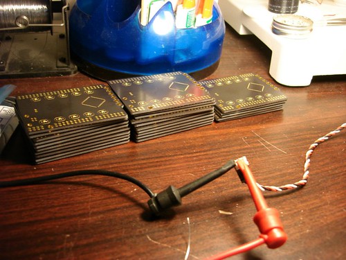
Here are all the boards lined up after their bath, getting ready for programming the bootloader:
This is the little connector that I put into the gold holes up at the front to program the bootloader - actually, this is a picture of Mike's hand, because while I washed 'em, he programmed 'em:
And when they're programmed, I put them all into little ESD bags:
So there you have it, now all the extra Illuminato's I had that were bought with "immediate" delivery will go out first thing in tomorrow morning's mail!
That was positively exhausting! But it was also pretty fun, since I really felt a sense of accomplishment building these things with Mike. I wouldn't trade it for the world. There's just something that "clicks" when you see a sketch turn into a circuit, into a pcb layout, into a real board, followed by a functional, working real live thing. In retrospect, I'd almost go as far as to propose a new version of the "man and machine" feeling you get driving sometimes ... maybe a new phrase, like "man and circuit"?
What can I say? It's been a pretty long weekend :) Mike and I were literally holed up in CT building Illuminato's by hand, and have a couple of pictures to prove it!
I have to admit, to keep things a little interesting while soldering all those little LED's together, I had my itunes playlist running in the background with a few new songs from the pop list. Normally, I wouldn't admit that kind of thing in public, but I suppose the solder fumes are getting to my head.
So since I now know all the lyrics after about 70 times on repeat, I figured it was only fitting to make a nerdy tribute to Beyonce's "If I were a boy" song ... so here's a little program that flashes the lyrics of the song in Morse Code in sync with the real song, and it does so by blinking the white LED's on the backside of the Illuminato, called with the bling(ON) and bling(OFF) commands. I've included the source code, which of course contains a complete morse ASCII-to-morse encoder.
And yes, at the end of the app, I appended a few extra letters... just for fun. :-) I also uploaded all my code to the app store here. This app has zero practical purpose, except maybe if it had a Lithium Backpack on the other side, you could carry it in your pocket, in case you need to communicate with a U-boat or signal mayday or signal for help from the Titanic and the date is 1920 and they can somehow decode +60 Morse code words per minute, visually not auditorily, and they're not weirded out by the fact that you're saying "If I were a boy, I think I could understand how it feels to love a girl I swear I'd be a better man." I think that rules out everyone. And even if they did, they'd probably leave you alone anyway.
Here's a snapshot of the morse code decoder code:
void morse( char m) { switch (m) { case 'A': case 'a': dit();dash(); break; case 'B': case 'b': dash();dit();dit();dit(); break; case 'C': case 'c': dash();dit();dash();dit(); break; case 'D': case 'd': dash();dit();dit(); break; case 'E': case 'e': dit(); break; case 'F': case 'f': dit();dit();dash();dit(); break; case 'G': case 'g': dash();dash();dit(); break; case 'H': case 'h': dit();dit();dit();dit(); break; case 'I': case 'i': dit();dit(); break; case 'J': case 'j': dit();dash();dash();dash(); break; case 'K': case 'k': dash();dit();dash(); break; case 'L': case 'l': dit();dash();dit();dit(); break; case 'M': case 'm': dash();dash(); break; case 'N': case 'n': dash();dit(); break; case 'O': case 'o': dash();dash();dash(); break; case 'P': case 'p': dit();dash();dash();dit(); break; case 'Q': case 'q': dash();dash();dit();dash(); break; case 'R': case 'r': dit();dash();dit(); break; case 'S': case 's': dit();dit();dit(); break; case 'T': case 't': dash(); break; case 'U': case 'u': dit();dit();dash(); break; case 'V': case 'v': dit();dit();dit();dash(); break; case 'W': case 'w': dit();dash();dash(); break; case 'X': case 'x': dash();dit();dit();dash(); break; case 'Y': case 'y': dash();dit();dash();dash(); break; case 'Z': case 'z': dash();dash();dit();dit(); break; case '1': dit();dash();dash();dash();dash(); break; case '2': dit();dit();dash();dash();dash(); break; case '3': dit();dit();dit();dash();dash(); break; case '4': dit();dit();dit();dit();dash(); break; case '5': dit();dit();dit();dit();dit(); break; case '6': dash();dit();dit();dit();dit(); break; case '7': dash();dash();dit();dit();dit(); break; case '8': dash();dash();dash();dit();dit(); break; case '9': dash();dash();dash();dash();dit(); break; case '0': dash();dash();dash();dash();dash(); break; case '/': dash();dit();dit();dash();dit(); break; case '+': dit();dash();dit();dash();dit(); break; case '=': dash();dit();dit();dash();dit(); break; case '.': dit();dash();dit();dash();dit();dash(); break; case ',': dash();dash();dit();dit();dash();dash(); break; case '?': dit();dit();dash();dash();dit();dit(); break; case '(': dash();dit();dash();dash();dit(); break; case ')': dash();dit();dash();dash();dit();dash(); break; case '-': dash();dit();dit();dit();dit();dash(); break; case '"': dit();dash();dit();dit();dash();dit(); break; case '\_': dit();dit();dash();dash();dit();dash(); break; case '\'': dit();dash();dash();dash();dash();dit(); break; case ':': dash();dash();dash();dit();dit();dit(); break; case ';': dash();dit();dash();dit();dash();dit(); break; case '$': dit();dit();dit();dash();dit();dit();dash(); break; case ' ': waitalittle(); break; default: break; } }
Matt and Matt were so busy with the Illuminato that they forgot to blog about the work they've been doing over on the Liquidware site!
As more and more modules showed up on the site, I kept getting emails about whether a kit could come with a Slide (vs. Stealth), or a HiCap (vs. MeCap), or even a BasicSTAMP CoreBoard (vs. Duemilanove). When things just got too unwieldy, it was time to let everyone pick their own kits, and thus the gadget builder was born.
After several weeks of extreme Ruby coding, the Matts finally pulled it together. There are three "base" kits - the Gadget Base, the Game Base, and the Robot Base, each of which can now be customized for almost every option anyone's asked for so far! Of course, it's still in beta, but it should work on Macs...be sure to check it out, and of course, just let me know if you've got questions :-)
Well, I only have a couple left from the initial set of boards I made, so Mike recommended that I put the price up a few dollars for the last ones if anyone really wanted one soon, until I make more in the next batch (probably one more month). I also heard a lot of people asking about in-circuit programming, which I'm going to do more research about (I thought no one ever used it, but it seems like some people really miss it... I just don't know too much about how it's used besides programming the chip initially). As for PWM, I'm also going to have to do more research on that, since I haven't really used it much before (right now, I wired 1 of the 4 to the backlight, leaving 3 left).
But before I get too far ahead of myself, I wanted to make sure I clarified something... I definitely, definitely could not have done this by myself! Thank you:
-Chris Ladden (website?) for his ideas on "circuit-design aesthetics" -Mark S. from Rutgers for meeting up in New Haven the last few weeks and teaching me the real way to write C programs (and for laughing at my BitDJ code) -Mike for teaching me CAD layout (slowly and very painfully) -Phil and Paul or inspiring me to release everything GNU GPL "Open Source" -Limor for convincing me that since everything is Turing Complete to begin with, it's all Open Source anyway and will run on a pile of river pebbles (ok, taken out of context, :-) but still influential - ha ha) -David Mellis and Tom Igoe from arduino.cc for helping me early on understand the processing / arduino / physical computing metaphor -NYC resistor because... I'm jealous you have real space to do work like this and I'm still doing this from my apartment... and the solder fumes are making me less smart :-)
...and of course, special thank you to my mentor who gave me some money to play around with and to actually build this board in the first place.
Well, now it's time to go solder these all up now... I think it'll probably take me the rest of the week, so that means I'll probably mail them out first thing next week. In the meantime, if I make good progress, I think I'm going to head over the Mike's house this weekend to play with his robot projects :)
It's been a few weeks since my last two posts, on How would you change the Arduino Part 1 and Part 2. And now I'm all done, and even have a couple boards in, hand-soldered and hand assembled ... I'm going to be building up a few of them over the next two weeks, so if you want one, I just put it up for sale over at liquidware shop for $29.95.
Anyway, I got a lot of emails and some comments on the blog about things to change and alter, and I tried to include as many as possible. Mainly, I focused on the following list:
-Code compatibility, works with IDE (backwards compatible with Arduino sketches) -More digital I/O (for LED matrices and robotics) -More code space -Faster PC transfer and serial speeds -PWM (interrupt driven pulse width modulation for servos) -Fits Arduino shields (like Ethernet Shield and XBee board) -In circuit programming interface (for debugging) -Works with TouchShield and GamePack (of course!)
Mostly, though, I wanted to make sure I helped out my old professor / mentor by making a board with more I/O, which is what he wanted for his class. On the way, I used the Atmega645, which has twice the code space, and a much faster code download speed. To be perfectly honest, the circuit schematics were actually the easiest part. The biggest challenge in the whole experience was trying to figure out how to keep the Arduino shape, and also allow it to work with the TouchShield Slide, Stealth and other shields out there. Here are some early idea sketches as I brainstormed the format:
After I had a rough idea of what I was looking for (you can tell some of the ideas didn't make it to the actual board), Chris showed me how to lay out parts using the PCB trace and layout software. The coolest part was that he had a program that lets you view the file in 3d in before you actually build it... so I used it just like I would have a drawing program (I don't know why no one's done this before):
Anyway, here it is! (I took some pictures with my personal camera at Starbucks this morning, and with Matt's insanely nice SLR camera too ... in my "ghetto" homemade lightbox which is still standing!)
On the back side I put 10 white surface mount LED's, encased in gold solder mask, which turn on and off with the bling() function. I also organized everything on the board to be perfectly symmetrical, yet 45 degrees rotated so that it looks like something out of Terminator 2.
The row of gold-lined aerodynamic holes up at the front of the board server two purposes:
1) reducing drag when the board flies over 200 mph :) and
2) they also double as in-circuit programming pins, so that I can program the Atmel chip with the initial bootloader
There's a reset button up in the corner, but the biggest change is the fact that it has 42 I/O pins in a configuration that accepts any shield that was made for the Arduino's pin header arrangement.
Since the whole point of it was to make a board with lots more I/O to interface to things like an LED matrix, I figured... why not wire up an LED matrix (this is before I realized how time consuming it is to actually sit there with tweezers and wire up a whole set of 24 wires):
Done!
Here's a video of it running a complete LED matrix with 24 input pins all from wires sitting down on the board - I've uploaded the source code over at the app store:
I'm especially thankful to Chris for his help making core files so I could just program the Illuminato from the Arduino IDE environment, by selecting the core from a drop-down. I'll post an update with a link to his files as soon as I'm done. In the meantime, I've written a small pocket-reference for myself so I remember all the new pin numbers (click here to see the bigger version - it's also on the wiki):
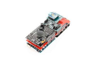
After hours of slaving over boring and confusing data sheets at digi.com and hours of tinkering with annoying chat programs and "AT" commands, I finally got 2 XBee Shields to communicate with each other!
I will now go through the painful preliminary steps I did to setup my xbee network.
Download X-CTU from Digi's website (And installed it... yeah, I installed the updates)
Repeat for both computers
Put both Arduinos in Reset
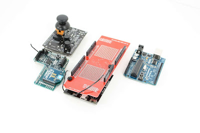
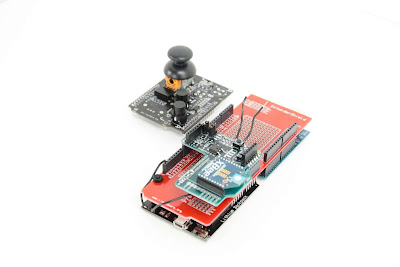
Attach the XBee Shield to the Arduino
Attach a USB cable from one arduino to Computer "A"
Attach the other USB cable to the other arduino and Computer "B"
Open X-CTU on Computer A
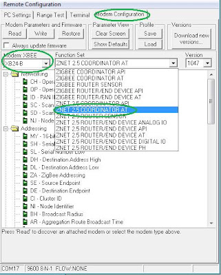
Go to the "Modem Configuration" tab... set the Modem: XBEE to "XB24-B" AND set the Function Set to "ZNET 2.5 ROUTER/END DEVICE AT"
Next is the Networking and Addressing Parameters...
PAN ID = 1111
Scan Channels = 15 (not sure if this is even needed)
Channel Verification = 0 (also not sure if this is even needed)
Destination Address High = 13A200 (I found this out by typing "AT" commands into a terminal program... first type in "+++" the xbee will return an "OK" you are now in command mode... if you type "ATSH" then "" (enter), the xbee will give you it's own high address (source address) )
Destination Address Low = 403E2502 (I found this out by typing "AT" commands into a terminal program)
Broadcast Radius = 0
Click the "Write" button on the Modem Configuration tab and wait for the XBee to program
If some funny error comes up... click the button on the xbee shield and try to program it again
Go to the "Modem Configuration" tab on computer B... set the Modem: XBEE to "XB24-B" AND set the Function Set to "ZNET 2.5 COORDINATOR AT"
Next is the Networking and Addressing Parameters for the XBee attached to computer B...
PAN ID = 1111
Scan Channels = 15 (not sure if this is even needed)
Channel Verification = 0 (also not sure if this is even needed)
Destination Address High = 13A200 (I found this out by typing "AT" commands into a terminal program... first type in "+++" the xbee will return an "OK" you are now in command mode... if you type "ATSH" then "" (enter), the xbee will give you it's own high address (source address) )
Destination Address Low = 404A4FC4 (I found this out by typing "AT" commands into a terminal program)
Broadcast Radius = 0
Click the "Write" button on the Modem Configuration tab and wait for the XBee to program
If some funny error comes up... click the button on the xbee shield and try to program it again
whew... now both devices are configured properly... open the X-CTU terminal tab of each computer... type and see the characters fly from pc to pc
I would like to thank the help of the following people...
There's something really aesthetically pleasing about the white on blue... I don't know what it is: I don't know how to take a photo of something white on a white background... so it's still a little grayed out :(
This one shows off the mirrored color scheme of red protoboards on a black extendershield, and vice-versa: This is probably my favorite picture I've ever taken:
The little red part of the TouchShield slide's connector makes this picture pretty neat to look at in high resolution (on flickr). The oscillator crystal on the left is pretty neat too:
Ok, so this coming year is definitely going to be a colorful one (pun... ugh... yeah yeah). And Chris and I are almost done working on image uploading for the Slide. In the meantime, I've finally gotten around to posting them on the shop, so I'll make an "official" blog post with all the specs soon!
 Started Programing as soon as I sat down


 I will now go through the painful preliminary steps I did to setup my xbee network.