Monday, May 31, 2010

Up and running on the Humidity Sensor

Mike, Matt and I had a blast out at the Bay Area Maker Faire in San Mateo last week. It was great to put some faces to names, and talk to fellow hackers in person.

I had a couple folks asking about their Arduino greenhouse projects, and they mentioned it might be useful to have a humidity sensor to make sure the room didn’t get too dry.

So Paul and Chris built the Humidity Sensor, which is really a Humidity and Temperature Sensor, since it provides an integrated temperature reading as well. I’ve uploaded it over at the Liquidware  and Modern Device shop pages.
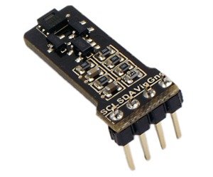
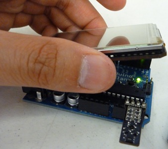
SONY DSCThe Humidity (and Temperature) Sensor is a board that carries the SHT21 digital humidity and temperature sensor from Sensirion. It has 4 pins that can mount directly on the Arduino’s analog pins. Two of the four pins are Ground and +5V; the other two are clock and data pins making up the 2-wire serial interface.

It transmits data to the Arduino over an I2C protocol, and comes with built-in 5V tolerance to be powered directly from the analog pins. The Antipasto Arduino IDE has an integrated library that makes the humidity sensor plug-and-play.

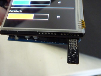
Here’s a quick demo that Will and I put together, which maps out the relative humidity and temperature as a bargraph on the TouchShield Slide. Because the Slide doesn’t occupy any of the Arduino Duemilanove’s analog pins, I was able to mount both the Humidity Sensor and the Slide directly onto the Arduino.P1000587
P1000582

I took a video of the Humidity Sensor bargraphs in action:

And the code is below:

//Humidity sensor bar graphs - Arduino Code
#include <Wire.h>
#include <LibHumidity.h>
#include <HardwareSensor.h>
int h;
int t;

LibHumidity humidity = LibHumidity(0);

void setup() {
  Sensor.begin(19200);
}

void loop() {
h = (int)humidity.GetHumidity();
t = (int)humidity.GetTemperature();
Sensor.print("humidity", h);
Sensor.print("temp", t);
delay(5);
}

________________________________________________

//Humidity sensor bar graphs - TouchShield Code
#include <HardwareSensor.h>
int newT;

void setup() {
  Sensor.begin(19200);
  background(0);
  line(0, 120, 320, 120);
text("RHumidity:", 0, 50);
text("Fahrenheit:", 0, 140);
}

void loop() {
if (Sensor.available()) {
   int h;
   int t;
if (!strcmp(Sensor.getName(), "humidity")) { 
h = Sensor.read();

fill(0);
text(h, 230, 80);
delay(10);
fill(0);
rect(0, 70, 200, 30);
{
fill(0, 0, 255);
rect(0, 70, h*2, 30);
}
}

if (!strcmp(Sensor.getName(), "temp")) { 
t = Sensor.read();

//convert celcius to fahrenheit
newT = (t*1.8 + 32);

fill(0);
text(newT, 230, 170);
delay(10);
fill(0);
rect(0, 160, 200, 30);
{
fill(255, 0, 0);
rect(0, 160, newT*1.6, 30);
   }
  }
}
}

Will’s posted the PDF cheatsheet over here, and I’ll be starting a greenhouse project next week with a couple of Arduino sensors including this one, so I’d love to hear any advice from any hackers out there with a green thumb :)
Friday, May 7, 2010

I’m going to Maker Faire (again)!

This past year, I’ve definitely been going to a few more Maker events in New England: Providence, New Haven, and just last week in Boston. It’s always nice to see what other folks are up to, meet other like minded people, and get some ideas for my next project.

A lot of it started with my trip out west last year to the Bay Area Maker Faire in San Mateo. It’s not quite a hackfest as it is the ultimate Maker meetup, and it was pretty mindblowing to see just how many creative projects could fit under a single roof.

Of course, the best part is always the people, and I’m starting to feel like it’s that one time of year where I finally get to catch up with some West Coast makers face to face.

So I’ll be back again this year, as maker #3399 with a few fun projects, including the Gravitational Drive RC Car, and I even decided to print up a vinyl banner for my table (which will be a nice tapestry in my room when Maker Faires aren’t going on :)

Arduino modules and sensors everywhere

The idea is for the table to be pretty interactive and hands-on, so there should be plenty of sensors and other toys as well. Paul lent me a box of some of his projects over at Modern Device, so I’ll have those too.

Anyway, I am packing my Maker Faire box with everything that I’m going to ship out there, so let me know if there’s anything else I should bring – jhuynh at gmail…

Monday, May 3, 2010

Automatic Screen Brightness with TouchShield and Light Sensor

Last week, I talked about the light sensors in my iPhone and old Blackberry that would automatically brighten or dim my screen based on the amount of ambient light. (Of course, that’s not to be confused with IR emitter/sensors that shut off the screen altogether when the phone is held to the face). Here’s the diagram of the iPhone that I borrowed from Wikipedia:imageSo Will emailed me, suggesting that maybe something like that could work with the TouchShield Slide and the AMBI Light Sensor, and that it could automatically set brightness based on ambient light to conserve energy.
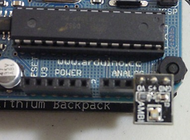
The basic idea would be to read data from the Light Sensor using the Antipasto Arduino IDE’s HardwareSensor library, and then use the Slide’s setBrightness() function to dim or brighten the screen based on the amount of ambient light.

First, I placed the light sensor on the Arduino’s analog pins 3, 4, and 5. Analog pin 3 is where the light sensor will output information. I used Analog 4 as Vin (High) and Analog 5 as my Ground (Low).

Light Sensor on Arduino Analog Then I plugged the Lithium Backpack’s +5V and Gnd directly into the power pins on the TouchShield Slide

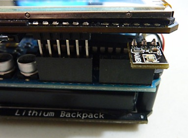
5V and Ground on TouchShield Slide …and mounted the TouchShield Slide onto the setup, which works nicely since the Slide doesn’t use any of the Arduino’s analog pins:

TouchShield Slide Light Sensor mounted on Arduino

Then I modified code from the Light Sensor Cheatsheet (PDF) to read data directly from the Light Sensor to the Slide. This snippet below goes to the Arduino:

#include <HardwareSensor.h>

void setup() {
  Serial.begin(9600);
  Sensor.begin(9600);
  pinMode(18, OUTPUT);
  pinMode(19, OUTPUT);
  digitalWrite(18, HIGH);
  digitalWrite(19, LOW);
}

void loop() {
int Light = analogRead(3);
Sensor.print("Light", Light);
Serial.println(Light);
}

Finally, I added a snippet of code to the Paint program that comes pre-loaded on the Slide (the full code is over in the App Store here). For the code that gets sent to the Slide, the HardwareSensor library needs to be included as well.

Then the following snippet goes into the loop() function:

// Light Read
if (Sensor.available()) {
    int Light;
  Light = Sensor.read();
  stroke(255);
  text(Light, 295, 230);
  }

// Change screen brightness based on light
if (Sensor.available()) {
    int Light;
Light = Sensor.read();
if (Light < 500) {
setBrightness(4);
} else {
if (Light > 500) {
setBrightness(0);
}    }
}

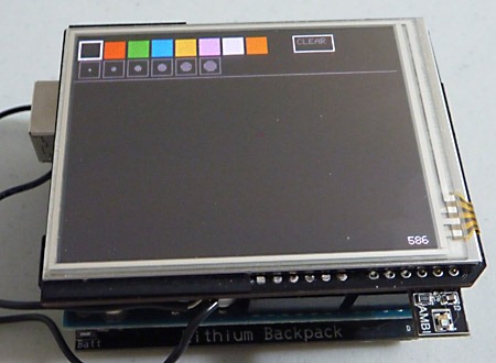
This code prints out the light reading as a number between 0 and 1000 on the lower right corner of the screen. Ambient light in my room is somewhere between 500 and 600, so I wanted the screen to brighten if it was any darker. Here’s a shot at 586, where the OLED is readily legible:

Light Sensor AutoBrightness Slide PaintAnd here’s a shot of the Paint program when the Slide’s screen brightness is automatically boosted at 396, when the room is a little dimmer. It’s actually much clearer by eye, but because of the low light, my point-and-shoot camera had a longer exposure (part of the reason for some blurriness, the other being my shaky hands :)

Light Sensor AutoBrightness Slide Paint Dark

I also took a video demo of the auto-screen brightness function in action: